|
|
|
Kto jest w sklepie?
Sklep przegląda 5930 gości |
|
Kategorie
|
|
Informacje
|
|
Polecamy
|
|
|
 |
|
|
Dla tego produktu nie napisano jeszcze recenzji!
 ;
Wszystko w porządku.
Instrukcja czytelna i kompletna.
Dziękuję.
all right!
thank you.
;
Bardzo dobra instrukcja. Zawiera wszystko co potrzeba, polecam!
 ;
Instrukcja jest OK. Schematy czytelne, opisane niektóre procedury.
;
Instrukcja bardzo czytelna. zawiera co potrzeba. Polecam
;
...instrukcja serwisowa w pełni czytelna i kompletna. Dziękuję!
MD-M3H
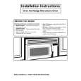
Lead-in switch position measurement mode
Insert High reflection test disk (TGYS1) Note: Adjust the lead-in switch position to FF85 to FFDF. 1. Loosen the screw (A) x 2 pcs. which fix the mechanism switch PWB. 2. Retighten the screw, pressing the mechanism switch PWB in the arrow direction, and then measure the lead-in switch position again. After position adjustment fix with the two screws (A). (See Fig. 21-1.) Note: After tightening the two screws on the PWB apply Screw Lock.
Loosen the two screws (A).
Lead In Switch
When STOP or EJECT appears in the display and the VOLUME CONTROL knob is rotated (up or down), it allows the loading motor to be forced to run (loading and unloading operations).
Forced rotation of loading motor
Mechanism Switch PWB
Figure 21-1
Adjustment of magnetic head mounting position
When the magnetic head and optical pickup have been replaced, be sure to adjust the mounting position. For easier adjustment of mounting position move the optical pickup to the center position, and then adjust the position. 1. Set the adjusting transparent disc 3. 2. Lower the magnetic head up-shift arm with your finger, and raise the magnetic head. 3. Viewing the set from above, make an adjustment so that the magnetic head aligns with the optical pickup objective lens. 4. Make sure that there is a clearance as shown in Figure 21-2 and the magnetic head moves up and down smoothly.
Magnetic head Tangential direction Objective lens Radial direction Push
Magnetic head
Figure 21-2
1
Mechanism Adjustment 1. Optical pickup grating inspecting method
43 Pin of IC1101 GND (TP1125) 100K 26 Pin of IC1101 EOUT (TP1129) 470p
GND CH1 CH2
3 2
OSILLOSCOPE
a
Spindle Motor
470p 25 Pin of IC1101 FOUT (TP1130) X 100K Y
b LISSAJOUS'S WAVEFORM Less than a:b = 4:1
Figure 21-3 Optical Pickup Grating Deviation Measuring Method
After the automatic adjustment has been performed in the AUTO mode (test mode) using the low reflection test disk MMD212 (TEAC) ("COMPLETE" will have been displayed), adjust the Lissajous waveform (x-y) using EOUT and FOUT. 1. Slightly loosen the 3 screws of spindle motor, and make an adjustment, observing the Lissajous's waveform. 2. After the adjustments are complete, tighten the screws in numerical order: 1 , 2 and then 3 . (See Fig. 21-4.)
Adjusting hole
3
Spindle motor
1
adjusting hole
2
Check the Lissajou's waveform, shifting the mounting position with a screwdriver (to be fitted into the disc motor adjusting hole).
Figure 21-4
� 21 �
|
|
|
> |
|